Why Overvoltage Protection Is Critical for Your Circuit (and 3 Ways to Add It)
Every electronics engineer eventually learns this lesson the hard way: you plug in power, a faint (or extremely loud) “pop” echoes through the room, and the circuit dies instantly.
That’s the story of overvoltage. It is when the voltage applied to your circuit exceeds what your components can safely handle. Whether it’s from a mis-wired power adapter, an inductive kickback, or a power surge from a bench supply, even a momentary spike can destroy sensitive semiconductors.
In professional designs, overvoltage protection (OVP) is not optional but a required part of reliability engineering. Adding overvoltage protection to your circuit is critical.
What Is Overvoltage?
Overvoltage occurs any time the voltage on a circuit node exceeds its safe operating limit. It can be:
- Continuous overvoltage, e.g. plugging a 24 V supply into a 12 V device.
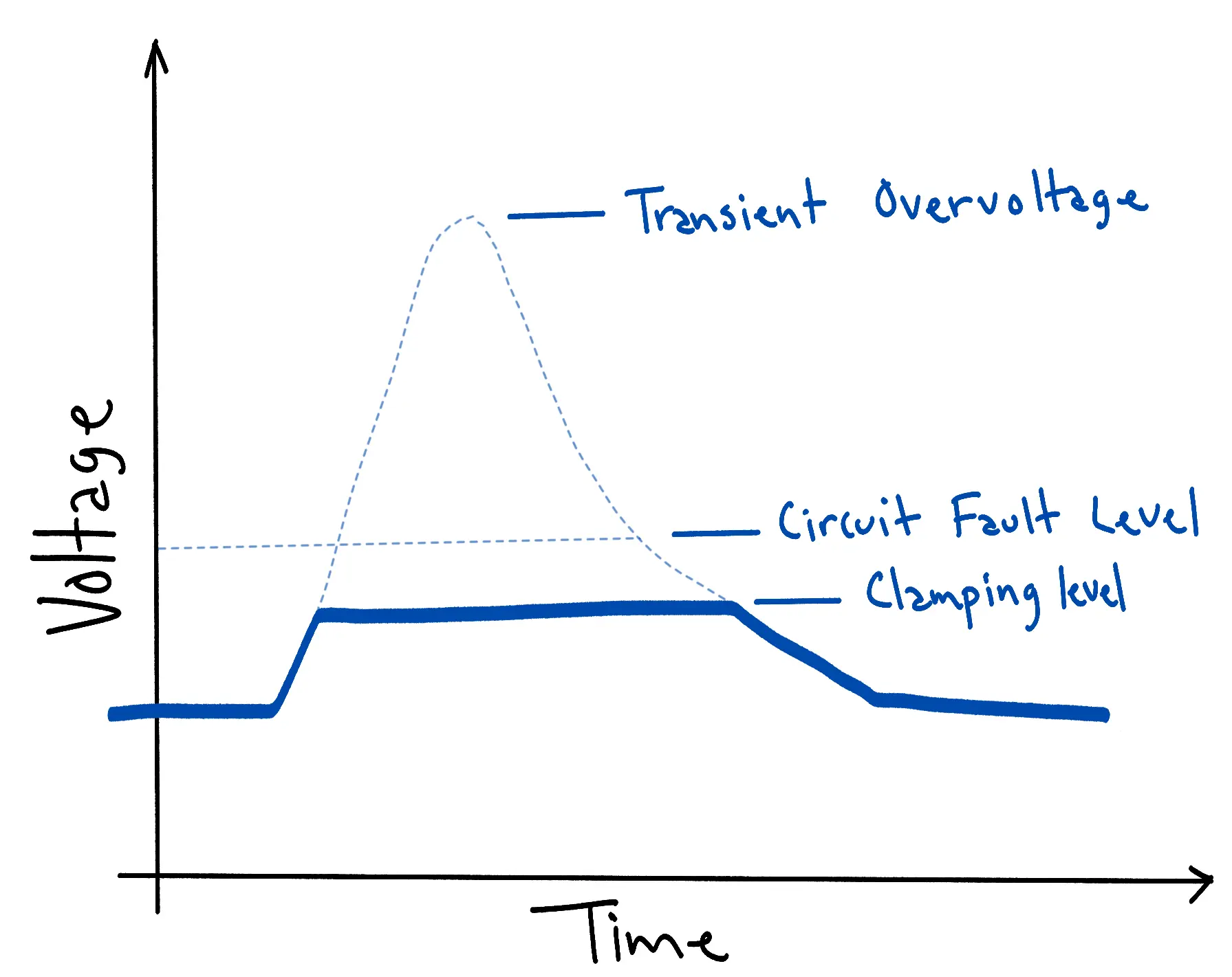
- Transient overvoltage, e.g. a spike lasting microseconds caused by an inductive load switching off or ESD (electrostatic discharge).
Both types can be damaging. Continuous overvoltage tends to overheat components and break down gate oxides, while transient spikes can punch through PN junctions, causing latent or immediate failure.
Why You Need Overvoltage Protection
- Prevents permanent damage
Components like voltage regulators, ICs, and MOSFET gates have absolute maximum ratings. Exceed them once, and they’re done. Even if the component seems to still work, it’s an unspoken industry rule that it must be replaced. You don’t want to cause your colleague or your future self any long hours of debugging. - Improves long-term reliability
Even if a spike doesn’t kill a part instantly, it can degrade it. Over time, this causes drift, leakage, or intermittent failures which is the worst kind to debug. - Protects against user error
Engineers and customers alike plug the wrong power supply into devices. Protection makes your circuit “idiot-proof,” and adds peace of mind so that you have one less thing to worry about in your design. Adding protection to internal and external testing infrastructure where the engineer is not the person setting up or operating the QC jigs is critical because it is impossible to account for all use cases and if the operators get creative, you don’t want to potentially be on remote debug calls till 3AM (It is not fun). - Saves time and money
In expensive designs, adding a hardware “insurance” device can save countless labor hours, money, and headaches. A small increase in BOM cost can prevent thousands in lost boards, warranty returns, and brand reputation damage.
3 Proven Ways to Add Overvoltage Protection
As described above, overvoltage protection important to protect your circuitry. Let’s look at three of the most common and effective protection methods, how they work, and their tradeoffs.
0. Fuses
I want to start by stating that a fuse on its own will not protect your circuit from overvoltage events. However, if the overvoltage carries significant energy, it can cause excessive current to flow through the fuse, which, depending on the fuse’s trip rating, may cause it to blow. This is not a reliable way to ensure that dangerous voltages never reach your sensitive circuitry. Even the best fuses can take around 100 ms to open at 1.5x their rated current. We get this question a lot.
1. TVS Diodes (Transient Voltage Suppressors)
How it works:
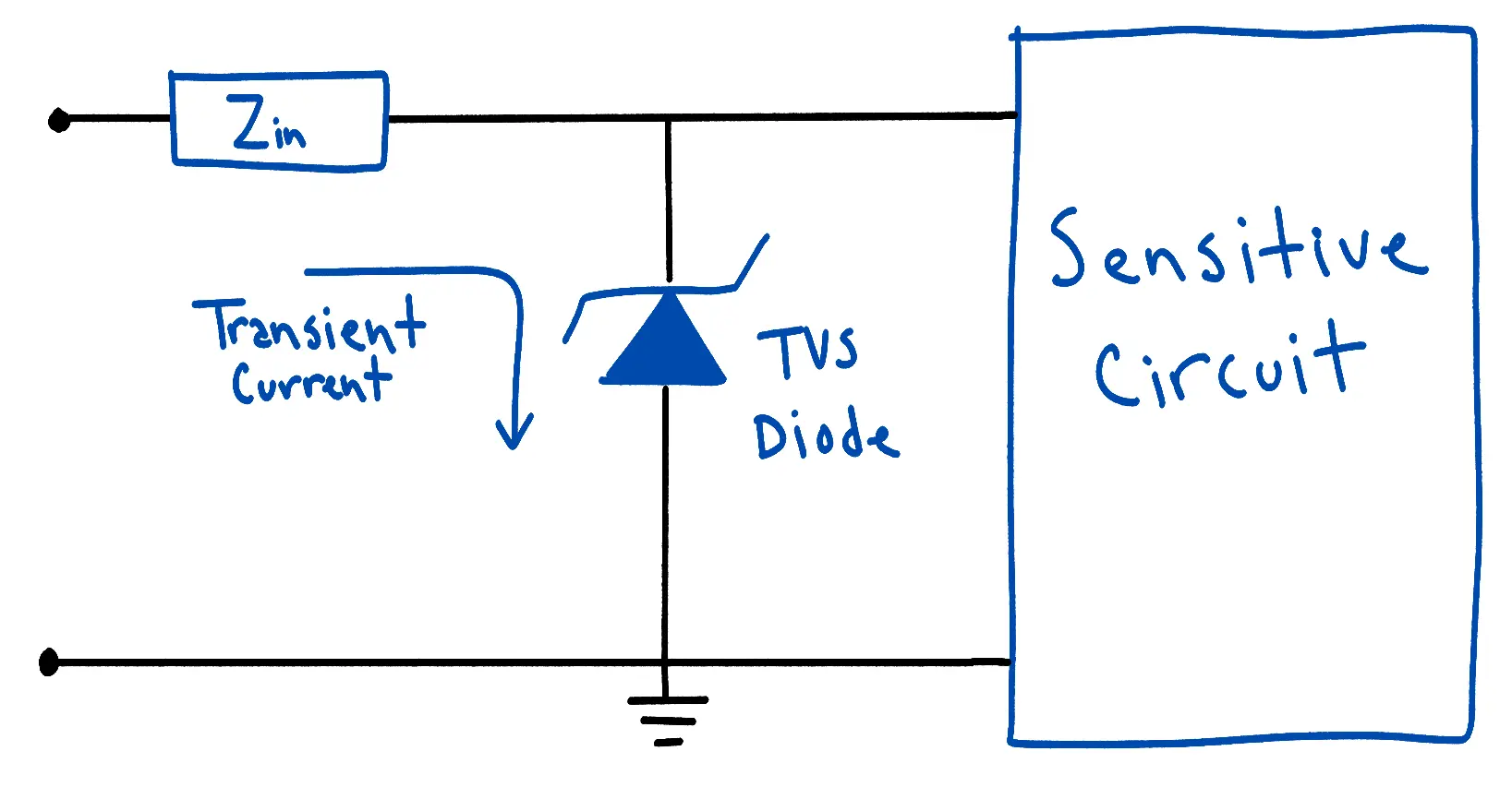
A TVS diode is like an electrical surge absorber. Under normal voltages, it sits quietly in reverse bias. When voltage exceeds its breakdown voltage, it conducts heavily, clamping the voltage to a safe level and absorbing surge energy.
Best used for:
- ESD and lightning protection
- Automotive or inductive load environments
- Power rails with occasional voltage transients
Pros:
- Extremely fast response time (picoseconds to nanoseconds)
- Simple two-terminal device makes it easy to add across power rails or signals
- Low cost and widely available
- Excellent for clamping brief, high-energy transients
Cons:
- Not suitable for sustained overvoltage (it will heat up and fail)
- Needs to be chosen carefully as full clamping voltage is usually much higher than the rated normal operating voltage
- Limited energy absorption (select by surge rating)
Pro Tip:
Always place TVS diodes close to the power input connector with a low-impedance ground return path to maximize effectiveness.
2. Crowbar Circuits (Zener + SCR)
How it works:
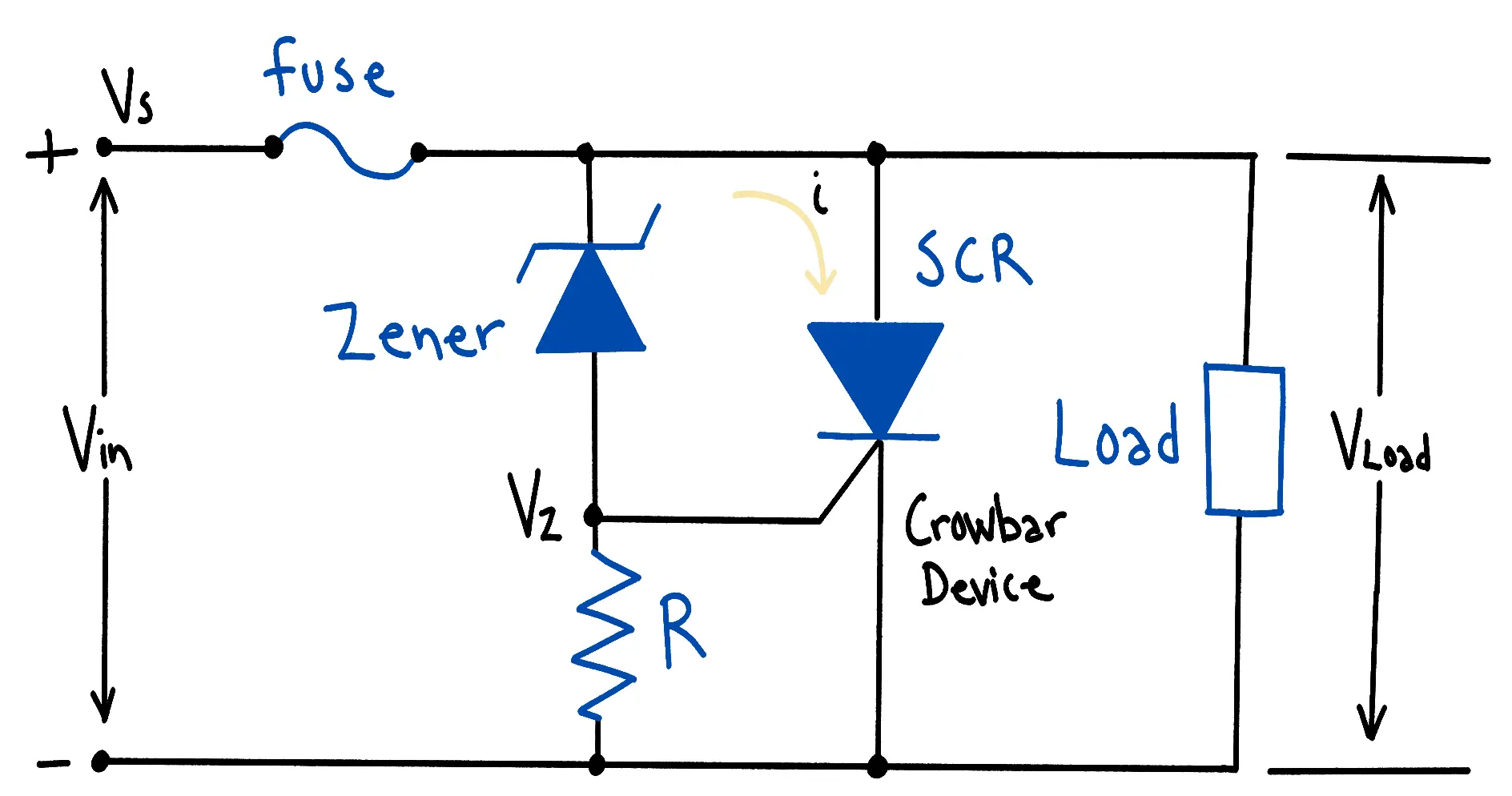
When the voltage exceeds a threshold (set by a Zener or reference), the crowbar circuit triggers the silicon-controlled rectifier (SCR) to short the supply to ground. This action “blows the fuse” or forces a shutdown, protecting the downstream circuitry. It’s a sacrificial but decisive protection method.
Best used for:
- Linear or lab power supplies
- Circuits where full shutdown is safer than operating above limits
- DC rails where a fuse or breaker is already present
Pros:
- Provides hard cutoff which has no ambiguity or slow degradation
- Simple analog design allows for no active monitoring needed
- Can handle large, sustained overvoltage events (if properly fused)
Cons:
- One-time action: circuit stays latched until power is cycled and depending on design, will require a fuse to be replaced
- Requires a fuse or series resistor to limit short-circuit current
- Not ideal for space-limited, low-power applications
Pro Tip:
Pair a crowbar circuit with a resettable fuse (PTC) or electronic fuse IC for reusability instead of physical fuse replacement.
3. Active Overvoltage Protection (Electronic Load Switches & Ideal Diode Controllers)
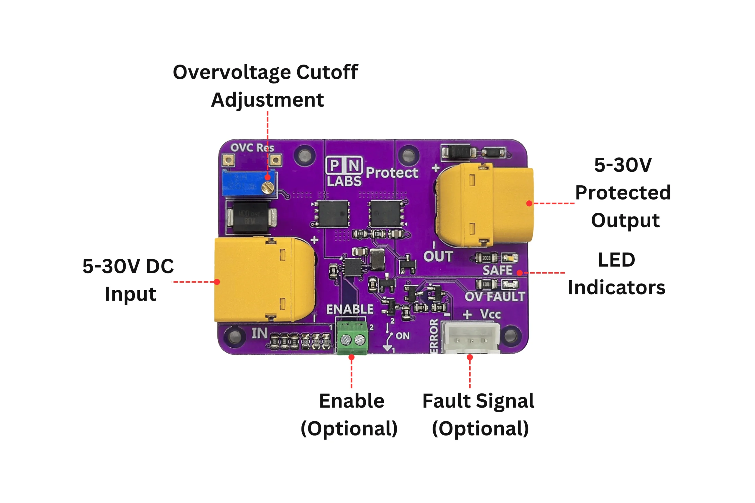
How it works:
Active protection circuits use dedicated ICs or modules that continuously monitor input voltage. When the voltage exceeds a threshold, the IC disconnects the load electronically. This is usually by turning off a MOSFET. Many also provide reverse-polarity and reverse-current blocking using ideal-diode control techniques.
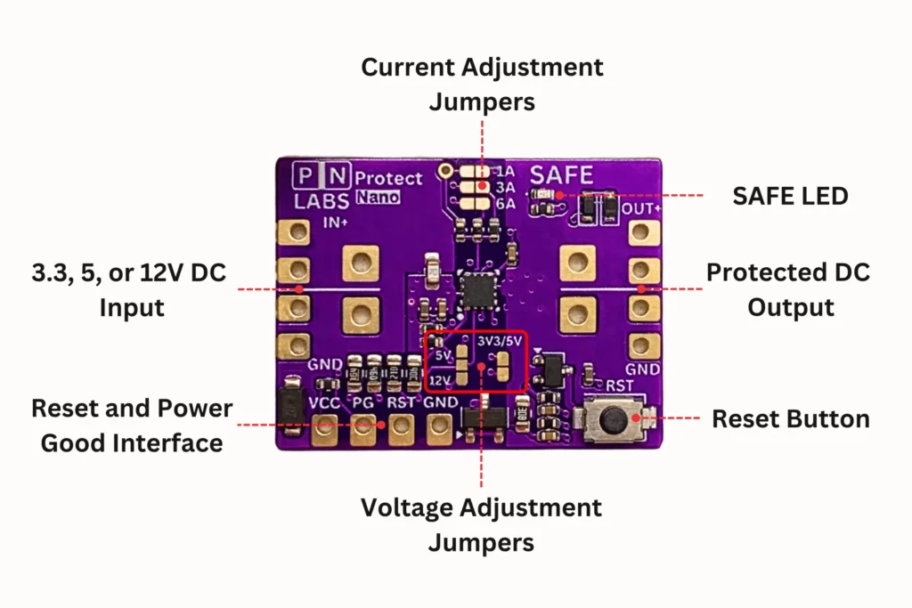
This is how modern protection modules like the PN Labs Protect and PN Labs Protect Nano operate: they combine multiple protection functions into one compact board.
Best used for:
- Sensitive digital systems, microcontrollers, and battery-powered devices
- Products that connect to external power adapters or multiple supplies
- Designs needing continuous, resettable protection without user intervention
Pros:
- Smart and automatic to reconnects when voltage returns to safe levels
- Handles both transient and continuous overvoltage
- Often includes reverse-polarity and reverse-current protection
- Reusable with no fuse replacement required
Cons:
- Slightly higher cost and complexity than passive solutions
- MOSFETs have a very small voltage drop (depends on Rds(on))
- Must be properly rated for maximum expected voltage and current
Pro Tip:
Use active protection modules on your main power input rail and pair them with TVS diodes or filters upstream for a complete defense.
Designing Robust Power Inputs
In professional and production-grade designs, engineers often combine multiple protection layers:
- TVS diode for fast surge clamping
- Active cutoff (like PN Labs Protect) for continuous overvoltage or misconnection
- Input filter and decoupling for noise and ripple control
This layered defense ensures your circuit stays safe from both brief surges and long-duration faults.
The Takeaway
Overvoltage protection isn’t just about preventing smoke, it’s about building resilience into your design. Whether it’s a DIY project or a mass-produced product, protecting your power input should be a first-class design goal.
If you’ve ever replaced a burnt regulator or watched a prototype die from a bad supply, you already know: it’s not a matter of if, but when. Adding overvoltage protection to your circuit is critical for reliability.
Looking for a Ready-to-Use Solution?
If you want plug-and-play overvoltage protection with reverse-polarity and reverse-current blocking built in, check out the PN Labs Protect or Protect Nano.
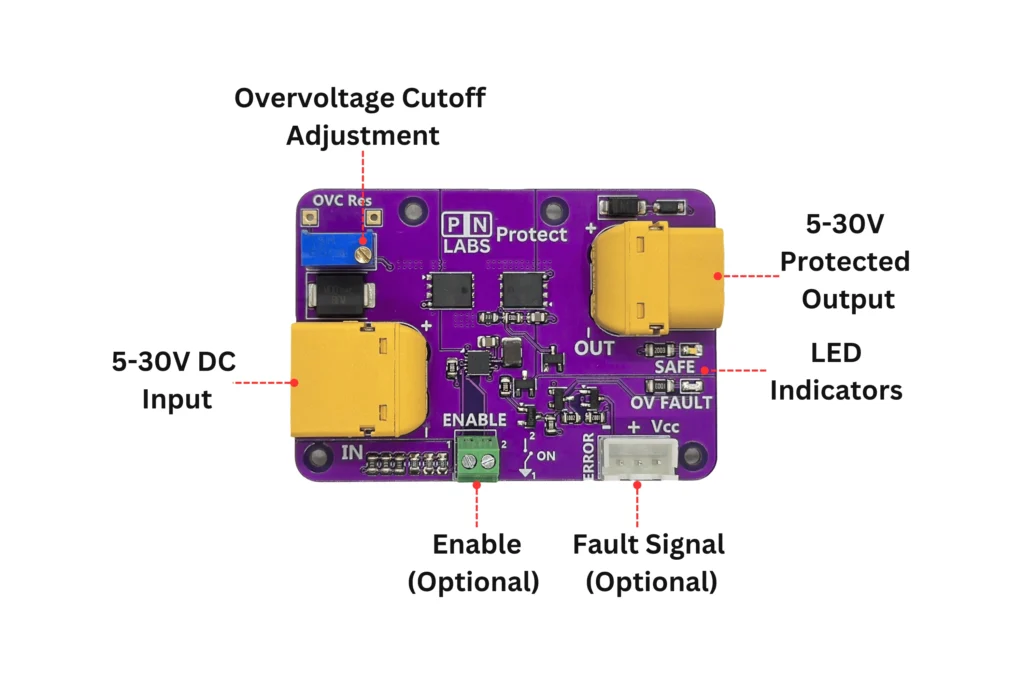
PN Labs Protect:
- 5 to 30V adjustable DC overvoltage adjustment range
- 25A Continuous Current Handling
- Load Switch with external switch
- Input reverse polarity protection
- Reverse current protection
- Fault signal output
- Led status indicator
PN Labs Protect Nano:
- Configurable overvoltage and undervoltage protection for 3.3, 5 and 12 V systems
- Adjustable 1, 3 or 6 A latching overcurrent limit with button or digital reset
- Breadboard compatible
- Perfect for embedded applications
- Input reverse polarity protection
- Reverse current protection
- Status LED (SAFE) and Power Good (PG) output