Protect+
Hardware-only DC protection for 7 to 60 V rails at up to 28 A, with every threshold adjustable.
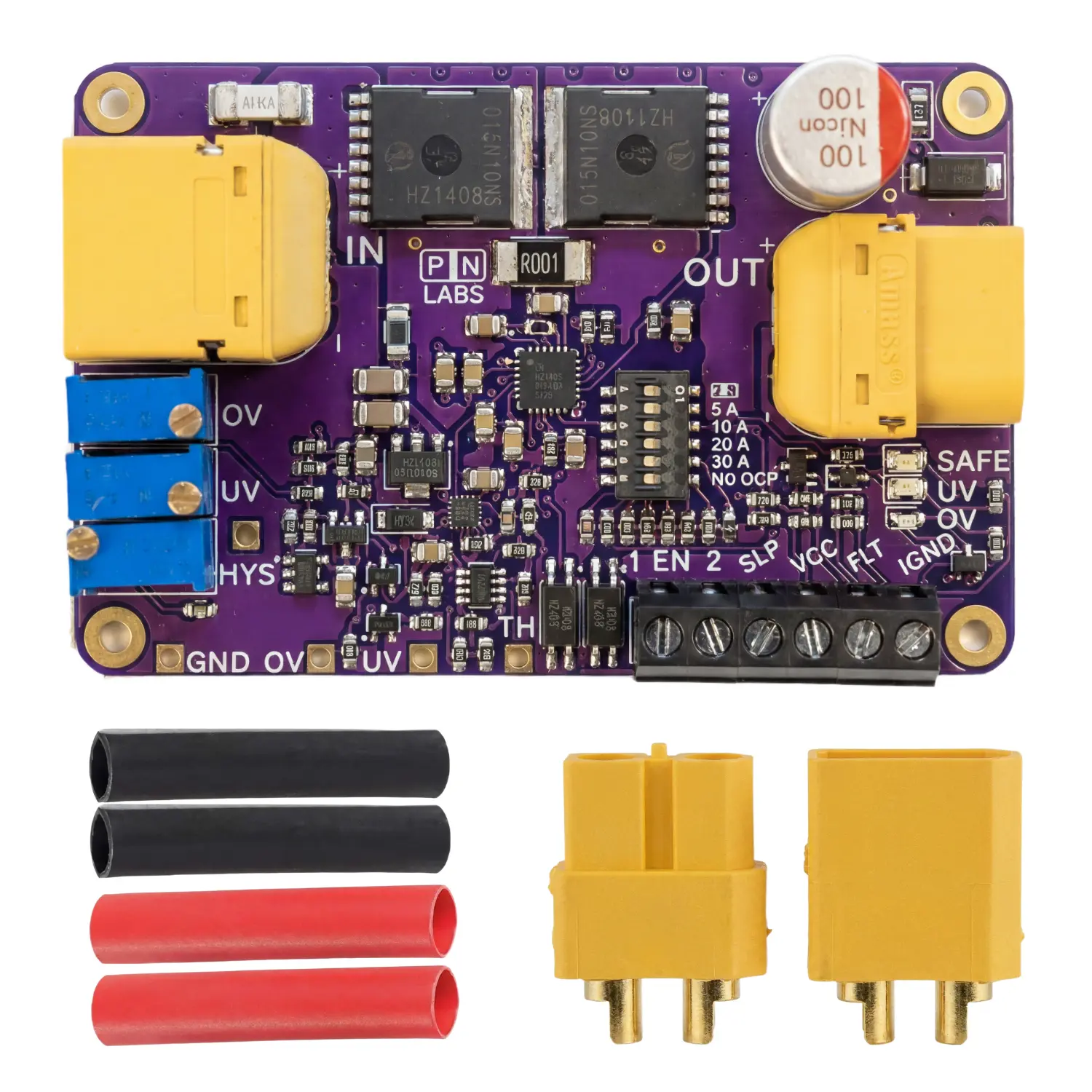
Protect+ combines adjustable overvoltage, undervoltage and overcurrent protection for 7–60 V DC systems up to 28 A. Reverse blocking supports redundant supplies, while isolated Sleep and fault signals give your controller access to on/off control and fault monitoring.
Description
- Adjustable Overvoltage & Undervoltage Protection (7–60 V):
Set independent cutoff thresholds for both high and low voltage events. When input voltage exceeds or drops below the configured limits, Protect+ automatically disconnects the load and restores power once conditions normalize. - Adjustable UVLO Hysteresis (0.45–5.68 V):
Dial in the right amount of undervoltage hysteresis to account for cable voltage drop, which is especially important with long or thin wires at high currents. Prevents unwanted chatter and power blips during recovery. - Latch-Off Overcurrent Protection:
Adjustable current cutoff selectable from 2, 5, 10, 20, 30 A or No OCP with ±10% typical accuracy and a ~50 ms response time. On an overcurrent event, the module latches off and waits for a manual or electronic reset, giving you full control before power is restored. - Reverse Polarity & Reverse Current Protection:
Ideal diode functionality blocks reverse current flow with minimal voltage drop, protecting against incorrect wiring and enabling safe paralleling of power supplies, batteries, or solar panels (power ORing). - Soft-Start Power-On:
Output voltage ramps gradually at approximately 0.2 V/ms after the UVLO threshold is cleared, protecting against inrush and ensuring the protection thresholds are evaluated before full voltage is applied. - 40 A Series Fuse:
A secondary layer of hardware protection on-board, guarding against conditions that could cause the pass MOSFETs to fail. - Power Switch Capability:
Use a low-current mechanical or digital switch via the Sleep input to toggle high-power loads. No bulky high-current switches required. - Opto-isolated Fault Output & Sleep Input:
Optional isolated open-collector fault signal for system diagnostics, alerts, or automated shutdown logic. Isolated sleep input allows external control of the module’s on/off state. - Compact & Mountable:
68 x 44 mm PCB with M2 mounting holes and XT60 connectors (with mating pair and heat shrink included) for easy installation.
Use volts for every value below. V_OV is the desired overvoltage trip point on a rising input. V_UV_recovery is the undervoltage recovery point on a rising input, and V_HYS is the gap between undervoltage trip and recovery. If you start with the falling trip point, add V_HYS to obtain V_UV_recovery.
- OV_pad = (V_OV − 0.092) / 30.47
- UV_pad = (V_UV_recovery − 0.047) / 30.53
- HYS_pad = (V_HYS + 0.058) / 29.89
- V_OV_recovery = 30.23 × OV_pad − 0.69
Measure the UV pad with the red LED on and the OV pad with the green LED on. OV hysteresis is fixed by the hardware: the last equation gives the falling input voltage at which the output recovers after an overvoltage trip.
Paralleling Protection Behavior
Why would you need to use a Protect+ module instead of just directly connecting in Parallel?
- When two unequal voltage sources are connected in parallel, the higher-voltage source will push current into the lower-voltage one, trying to bring them both to the same potential.
This uncontrolled current can damage supplies that aren’t designed to accept it, as the internal control loop of the lower supply now has to fight to compensate for what the other source is doing. In the case of a battery, an unregulated and potentially dangerous current spike can flow, possibly exceeding the battery’s maximum charge current, damaging it by plating lithium and contributing to early failure.
Each Protect+ module has an internal comparator that senses the voltage across its pass MOSFET and switches it off within microseconds if reverse current is detected, isolating that source and protecting whatever is behind it.
A note on load sharing: ORing gives you clean redundancy and fault isolation. If one source drops out, the others carry the load with no backfeed. It does not actively balance current between sources. For the sources to share the load reasonably at all, we’ve found they generally need to be within about 0.5 V of each other; the higher source will still tend to carry more of the load until it reaches its current limit.
To operate the Protect+ module in paralleling (ORing) mode:
- Use one Protect+ module per power source.
- Set the OVC (overvoltage cutoff) limit on each module, or disable it by turning the OVC resistor to maximum resistance.
- Connect each power source to its own Protect+ module.
- Join the output terminals of all Protect+ modules together to form the combined output.
- (Optional) Add a switch to the Enable terminal on each module to individually turn sources on or off
Additional information
| Operating Voltage | 7 – 60 V DC, with 65 V absolute max before damage to the Protect+ may occur. 100 V max Vds MOSFETs are used as the pass elements. |
|---|---|
| Maximum Continuous Power | 1700 W |
| Maximum Continuous Current | 28 A @ 25 °C ambient |
| HS code | 8536.30 |
| Country of origin | China |
| Export classification | EAR99 |
| Weight | 45 g |
| SKU | 9803 |